In March 2022 the UCIe Consortium published the UCIe 1.0 specification, defining a layered die-to-die interconnect built on top of PCIe and CXL semantics. UCIe 1.1 followed in 2023 with compliance-test enhancements, automotive-grade runtime repair and new bump maps. On August 6, 2024 the consortium released UCIe 2.0, adding 3D packaging support and the UCIe DFx Architecture (UDA) — a standardized management fabric that enables vendor-agnostic test, telemetry and debug across every chiplet in a package. On August 5, 2025 UCIe 3.0 was announced, pushing per-pin signaling to 64 GT/s and further hardening manageability. The consortium now counts 130+ member companies, including AMD, Arm, ASE, Google Cloud, Intel, Meta, Microsoft, Qualcomm, Samsung, TSMC, Alibaba and NVIDIA.
That ecosystem acceleration is exactly why 2026 is the year chiplet verification stops being a research topic and becomes a line item on every tapeout schedule. Once your package contains a CPU die from one foundry, an I/O die from another, HBM from a memory vendor and an optional optical I/O chiplet (see Ayar Labs’ 8 Tbps TeraPHY UCIe demo at OFC 2025), the UCIe physical layer is the only contract holding the system together — and SI simulation is how you prove that contract holds before you commit to a $2M+ silicon interposer tapeout.
What readers actually need to know
This article is written for three audiences that keep showing up in whychip.com analytics: (1) SoC architects scoping their first chiplet-based product, (2) package/SI engineers migrating from PCB-era tooling into 2.5D/3D flows, and (3) DV leads who own UCIe compliance. We’ll stay close to the published specification, cite the tooling vendors by name where relevant, and avoid made-up numbers — every performance figure below is traceable to the UCIe Consortium, Synopsys, Cadence, Keysight, Alphawave Semi, Siemens EDA, or peer-reviewed IEEE/IMAPS papers.
1. The UCIe stack in 60 seconds
UCIe is layered, deliberately mirroring the PCIe/CXL playbook so that existing protocol IP can be reused above the D2D boundary.
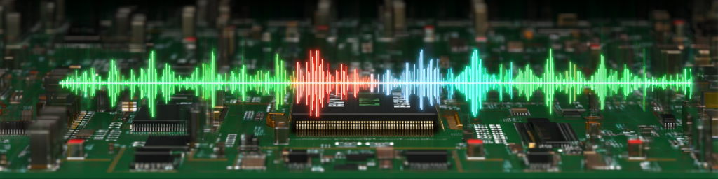
- Physical Layer (PHY) — electrical signaling, link training, sideband, lane repair. This is where signal integrity lives.
- Die-to-Die Adapter — link management, protocol arbitration, optional CRC + retry for BER hardening.
- Protocol Layer — carries PCIe, CXL (68B/256B flits), streaming and raw user-defined traffic.
The two PHY flavors every chiplet designer must choose between:
| Attribute | Standard Package (UCIe-S) | Advanced Package (UCIe-A) |
|---|---|---|
| Bump pitch | 100–130 µm | 25–55 µm |
| Channel reach | Organic substrate, longer reach | Up to ~2 mm on Si interposer / RDL |
| Per-lane data rate (UCIe 2.0) | 4, 8, 12, 16 GT/s (up to 32 GT/s) | 4, 8, 12, 16, 24, 32 GT/s |
| Termination | TX + RX terminated | TX driven, no RX termination |
| Target raw BER | 1E-27 at low rates, 1E-15 at ≥12 GT/s | 1E-27 at ≤12 GT/s, 1E-15 at 16/24/32 GT/s |
| Signaling | Unidirectional NRZ | Unidirectional NRZ |
Source: UCIe 1.1/2.0 Electrical, Form-Factor and Compliance material, UCIe Consortium, Hot Chips 2023 tutorial; Synopsys UCIe glossary.
The practical takeaway: UCIe-A buys you 10–20× shoreline bandwidth density over UCIe-S, at the cost of requiring a silicon interposer or advanced RDL, and pushing the entire SI burden onto an unterminated receiver — which is exactly why simulation is non-negotiable.
2. Why chiplet SI is not “just SerDes, but shorter”
It is tempting to assume that because UCIe channels are only 1–2 mm, signal integrity is easy. The IMAPS 2024 paper “UCIe Full Signal Integrity Analysis Flow with Compliance Check for Heterogeneous Integration” and the IBIS Summit 2024 talk “Chiplet Signal Integrity Simulation” both push back on that assumption with concrete data:
- A single UCIe-A link can aggregate 24 channels × 96 I/O = ~2,400 signals per die edge, all on a 55 µm bump pitch.
- Silicon interposers routinely use 2 µm trace widths and degassed (gridded) ground references — not solid planes — which dramatically changes return-current behavior versus PCB intuition.
- A typical interposer carries ~600 TSVs per UCIe region, each with its own impedance discontinuity.
- At standard-package distances of 10–25 mm on organic substrates, crosstalk dominates over insertion loss; eye closure from FEXT/NEXT is the #1 failure mode.
In short, UCIe SI is a dense, short, heavily-coupled, non-ideal-reference problem — closer to on-chip global routing than to PCIe on FR-4.
3. A reference UCIe physical-layer SI simulation flow
There is no single vendor monopoly here; the flow below is synthesized from publicly documented methodologies at Synopsys, Cadence, Keysight, Siemens EDA and Alphawave Semi. Read it as a competitive-landscape map as much as a methodology.
Step 1 — Channel extraction (3D EM)
- Extract the full die-bump → µbump → interposer/RDL → µbump → die-bump path using a 3D full-wave or hybrid solver.
- Representative tools: Cadence Clarity 3D Solver + Sigrity (used in the GOMAC 2025 UCIe flow), Ansys HFSS / SIwave, Siemens HyperLynx, Keysight ADS / EMPro.
- Capture degassed references, TSV arrays, and seal-ring proximity — all three are dominant contributors to mode conversion at ≥16 GT/s.
Step 2 — Channel compliance against the UCIe kit
- The UCIe Consortium publishes a compliance kit (reference TX/RX behavioral models, mask, jitter budget). Use it first — it is vendor-neutral and the gating check for interoperability.
- Run in tools like Keysight Chiplet PHY Designer (demonstrated with Alphawave Semi on UCIe compliance), Cadence SystemSI, or Synopsys HSPICE + StatEye.
- Outputs: statistical eye, COM-like margin, jitter decomposition.
Step 3 — Vendor-specific IBIS-AMI
- Compliance passing does not guarantee a given TX/RX pairing will close. Layer IBIS-AMI models from each chiplet vendor on top of the extracted channel.
- Per the IMAPS paper “Using UCIe Channel Compliance Simulation for Understanding Substrate Interposer Design Tradeoffs,” vendor equalization can shift margin by several mV of eye height — decide equalization strategy early.
Step 4 — Power-aware co-simulation
- UCIe’s low-swing CMOS PHY is acutely sensitive to supply noise. Co-simulate the PDN with the signal channel (Sigrity PowerSI/OptimizePI, HFSS + SIwave, HyperLynx PI).
- Target: simultaneous-switching-noise (SSN) induced jitter < the UCIe TX total-jitter budget at your chosen data rate.
Step 5 — Compliance, DFx and silicon correlation
- UCIe 1.1 introduced a test/compliance register block; UCIe 2.0’s UDA standardizes the management fabric so any chiplet can be probed for loopback BIST, eye margining and lane repair.
- Keysight’s public UCIe test enablement material describes a three-step “Golden Die” PHY validation: (1) measure the replica channel unpopulated, (2) populate one die and de-embed, (3) populate both dice, probe sideband, debug link bring-up.
- Correlate silicon eye/jitter back to the Step-2/3 simulation decks. Any >10% delta is your cue to revisit the extraction assumptions.
4. Competitive landscape: where the market gap is
From a survey of vendor blogs, conference tutorials and IEEE publications across 2024–2025, three gaps stand out for tool users:
- Cross-vendor IBIS-AMI exchange is still painful. Every vendor ships AMI, but packaging different vendors’ models into one compliance deck is manual. Expect scripting.
- 3D (stacked) UCIe SI tooling is nascent. UCIe 2.0 explicitly targets 3D packaging and UCIe-3D drops bump pitch toward 1 µm (per the Nature Electronics 2024 paper on UCIe-3D from Intel). Full-wave extraction at that density is compute-bound; HPC clusters running these sims routinely exceed $100k CapEx, per Signal Edge Solutions.
- Compliance ≠ Interop. The industry is only now moving from “Golden Die” BIST-based compliance to a true multi-vendor plugfest model, as discussed at Chiplet Summit 2025 and IMAPS CHIPcon 2025.
This is the editorial white space whychip.com can own: practical, reproducible flows that bridge the compliance-to-interop gap.
5. Frequently asked questions (voice-search optimized)
What is UCIe in simple terms?
UCIe is an open die-to-die interconnect standard — think “PCIe inside a package” — that lets chiplets from different vendors talk to each other at 4–64 GT/s per pin across a shared substrate or silicon interposer.
Why is UCIe physical-layer signal integrity so hard?
Because UCIe packs thousands of high-speed lanes into millimeter-scale channels on non-ideal reference planes, with an unterminated receiver in advanced-package mode. Small geometric changes in the interposer translate directly into eye closure.
What tools do engineers use for UCIe signal integrity simulation?
The most-cited commercial flows are Cadence Sigrity/Clarity/SystemSI, Synopsys HSPICE with UCIe VIP, Keysight Chiplet PHY Designer/ADS, Siemens HyperLynx, and Ansys HFSS/SIwave — typically combined with the UCIe Consortium’s compliance kit and vendor IBIS-AMI models.
What is the difference between UCIe Standard and UCIe Advanced packages?
Standard uses 100–130 µm bump pitch on organic substrates with both TX and RX terminated, good for longer reach. Advanced uses 25–55 µm bump pitch on silicon interposers or advanced RDL, supports up to 32 GT/s and does not terminate the RX to save power.
Does UCIe 2.0 support 3D packaging?
Yes. UCIe 2.0 (released August 2024) explicitly adds 3D packaging support and the UDA management fabric. UCIe 3.0 (August 2025) pushes signaling to 64 GT/s while remaining backward compatible.
How is chiplet interoperability actually verified?
In three concentric rings: (1) UCIe compliance kit + PHY compliance testing per the consortium; (2) pairwise IBIS-AMI channel simulation against the specific counterparty chiplet; (3) silicon-level Golden Die / BIST loopback, with DFx telemetry per UCIe 2.0 UDA once the SiP is assembled.
6. A practical 2026 checklist for chiplet DV teams
- [ ] Lock your UCIe profile (Standard vs Advanced, data rate, module width) before floorplan — it determines bump map and interposer rules.
- [ ] Stand up a 3D EM extraction flow early; do not wait for final interposer GDS.
- [ ] Run UCIe compliance-kit simulations at every interposer revision, not just final signoff.
- [ ] Ingest counterparty IBIS-AMI as a hard prerequisite for any external chiplet; no AMI, no integration.
- [ ] Budget PDN co-simulation alongside SI — SSN is the silent killer of UCIe margins.
- [ ] Wire UCIe 2.0 UDA telemetry into your post-silicon dashboards from day one; it is free DFx.
- [ ] Plan for a multi-vendor plugfest phase before high-volume assembly. Treat it as part of DV, not marketing.
Closing perspective
The chiplet era makes interoperability a physical-layer problem first and a protocol problem second. UCIe has given the industry a common vocabulary; what remains is the disciplined engineering work of simulating, measuring and correlating every millimeter of die-to-die channel across vendors that were never designed to co-exist. Teams that invest in a repeatable UCIe signal integrity simulation flow in 2026 will tape out working multi-vendor SiPs in 2027. Teams that skip it will debug in silicon — and that, at today’s advanced-package NRE, is the most expensive shortcut in our industry.
发表回复
要发表评论,您必须先登录。